
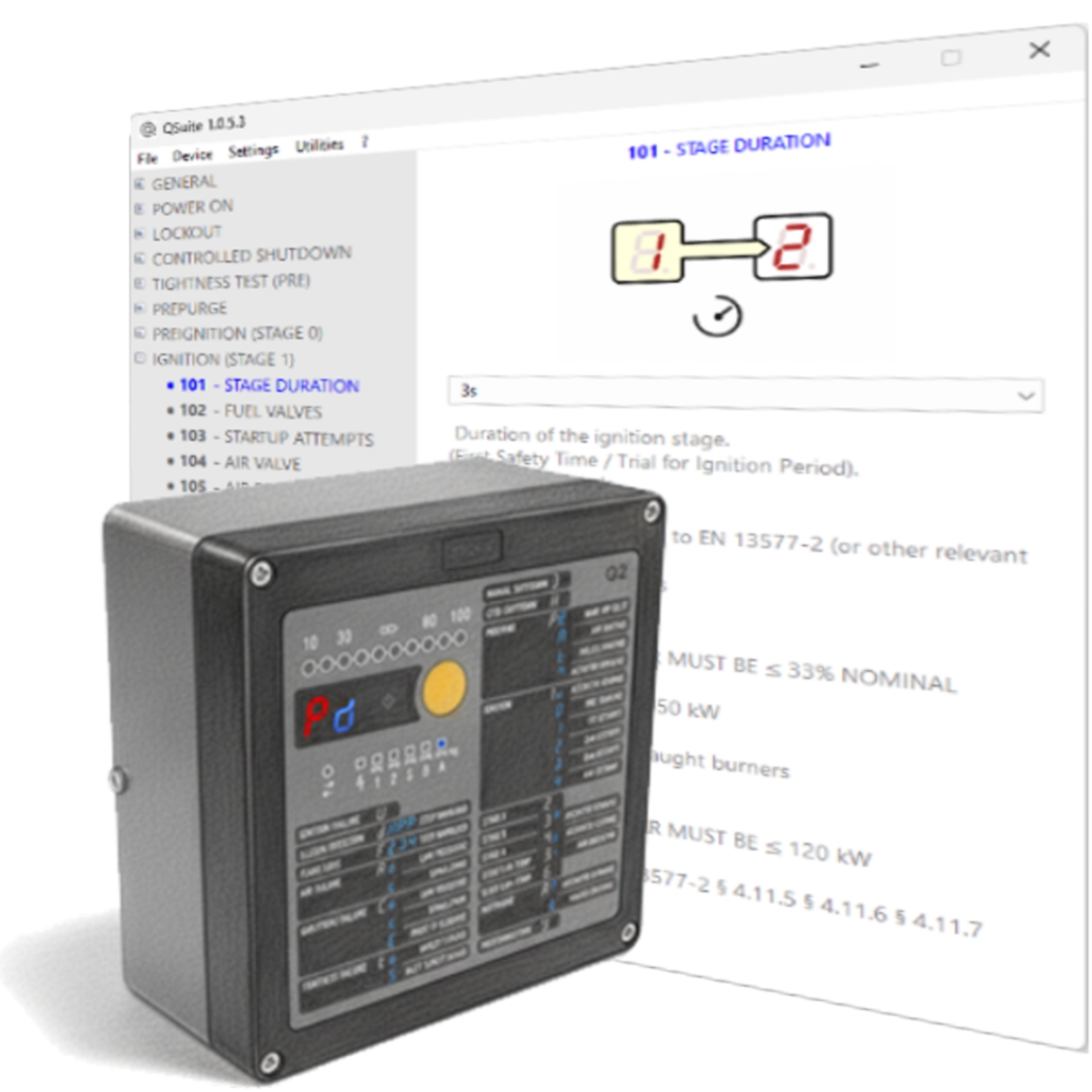

CONFIGURATION AND COMMISSIONING TOOL
No need to install.
You can even carry it on your USB drive anywhere you want.
Q.Suite is a free software tool for burner management systems based on the Q1 and Q2 burner control units suitable for:
• Reading and writing of configuration parameters
• Reading of operating statistical data
• Management of commissioning operations
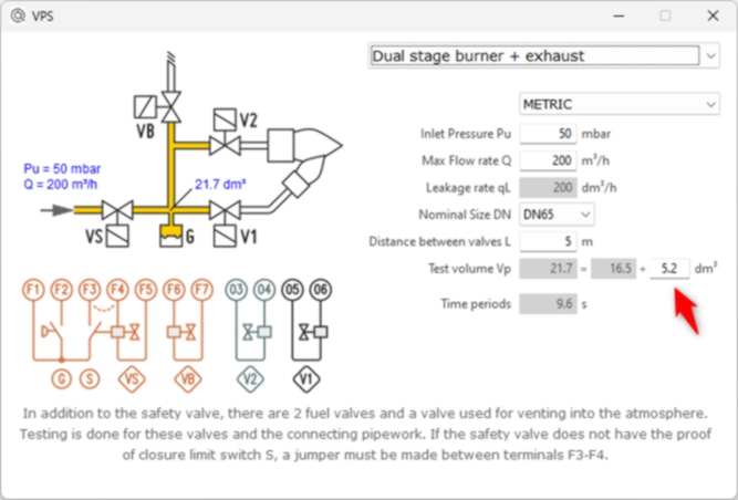
• Calculation of times for Valve Proving System
Configuration can be saved and retrieved from file and printed to local printer or text file.| CODE | |
|---|---|
THIS TAB SHOWS INFORMATION ABOUT THE DEVICE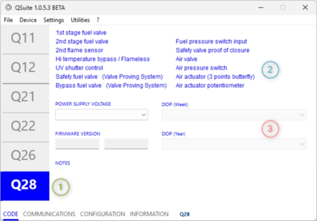
|
|
| 1 |
DEVICE TYPE If the data was retrieved from a device, the model is highlighted in the left column. When using Q.Suite to create a new device configuration, you can select the model by clicking the corresponding box. |
| 2 |
FEATURES The functions available for the currently selected model are highlighted in this area. |
| 3 |
DEVICE DATA If the data has been retrieved from a device, this area shows the production data and the power supply voltage of the linked unit. When using Q.Suite to create a new device configuration, this area allows you to select the desired power supply voltage. |
| COMMUNICATIONS | |
|---|---|
THIS TAB SHOWS THE DEVICE COMMUNICATION OPTIONS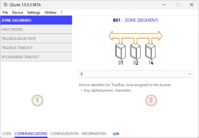
|
|
| 1 |
PARAMETER SELECTION If the data was retrieved from a device, the model is highlighted in the left column. When using Q.Suite to create a new device configuration, you can select the model by clicking the corresponding box. |
| 2 |
PARAMETER OPTIONS On the right is the information relating to the selected parameter, with the possibility of selecting your preference. |
| CONFIGURATION | |
|---|---|
THIS TAB SHOWS THE DEVICE CONFIGURATION OPTIONS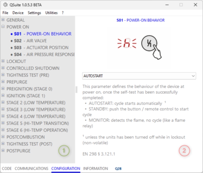
|
|
| 1 |
STAGES TREE VIEW On the left is the list of all operating stages, click on the + symbol to expand the view and show the parameters relating to the specific stage. After expanding the view, click on a parameter to view related options. |
| 2 |
PARAMETER OPTIONS On the right is the information relating to the selected parameter, with the possibility of selecting your preference. |
| INFORMATION • DEVICE | |
|---|---|
THIS TAB SHOWS THE OPERATIONAL STATISTICAL DATA DIVIDED INTO 3 SPECIFIC PAGES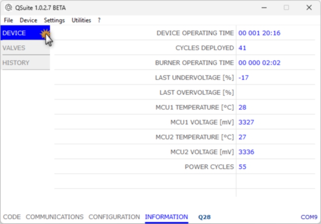
|
|
|
DEVICE OPERATING TIME THE TOTAL TIME THE DEVICE HAS BEEN OPERATIONAL (POWERED ON) - YY DDD hh mm:ss |
|
|
CYCLES DEPLOYED THE TOTAL NUMBER OF IGNITION CYCLES PERFORMED BY THE DEVICE |
|
|
BURNER OPERATING TIME THE TOTAL TIME DURING WHICH THE BURNER HAS BEEN OPERATING |
|
|
LAST UNDERVOLTAGE LAST DEVIATION FROM THE NOMINAL VOLTAGE GREATER THAN -15% (IF ANY) |
|
|
LAST OVERVOLTAGE LAST DEVIATION FROM THE NOMINAL VOLTAGE GREATER THAN +10% (IF ANY) |
|
|
MCU1 TEMPERATURE CURRENT TEMPERATURE OF MICROCONTROLLER 1 (-25...85°C) |
|
|
MCU1 VOLTAGE CURRENT POWER SUPPLY VOLTAGE OF MICROCONTROLLER 1 (3000...3500mV) |
|
|
MCU2 TEMPERATURE CURRENT TEMPERATURE OF MICROCONTROLLER 2 (-25...85°C) |
|
|
MCU2 VOLTAGE CURRENT POWER SUPPLY VOLTAGE OF MICROCONTROLLER 2 (3000...3500mV) |
|
|
POWER CYCLES THE TOTAL NUMBER OF TIMES THE DEVICE HAS BEEN TURNED ON |
|
| INFORMATION • VALVES | |
|---|---|
THIS TAB SHOWS THE OPERATIONAL STATISTICAL DATA DIVIDED INTO 3 SPECIFIC PAGES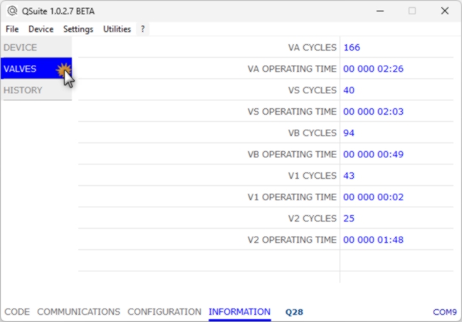
|
|
|
VA CYCLES THE TOTAL NUMBER OF TIMES THE AIR VALVE HAS BEEN TURNED ON |
|
|
VA OPERATING TIME THE TOTAL WORKING TIME OF THE AIR VALVE - YY DDD hh mm:ss |
|
|
VS CYCLES THE TOTAL NUMBER OF TIMES THE FUEL SAFETY VALVE HAS BEEN TURNED ON |
|
|
VS OPERATING TIME THE TOTAL WORKING TIME OF THE FUEL SAFETY VALVE - YY DDD hh mm:ss |
|
|
VB CYCLES THE TOTAL NUMBER OF TIMES THE MULTIFUNCTION BYPASS VALVE HAS BEEN TURNED ON |
|
|
VB OPERATING TIME THE TOTAL WORKING TIME OF THE MULTIFUNCTION BYPASS VALVE - YY DDD hh mm:ss |
|
|
V1 CYCLES THE TOTAL NUMBER OF TIMES THE V1 (PILOT) VALVE HAS BEEN TURNED ON |
|
|
V1 OPERATING TIME THE TOTAL WORKING TIME OF THE V1 (PILOT) VALVE - YY DDD hh mm:ss |
|
|
V2 CYCLES THE TOTAL NUMBER OF TIMES THE V2 (MAIN) VALVE HAS BEEN TURNED ON |
|
|
V2 OPERATING TIME THE TOTAL WORKING TIME OF THE V2 (MAIN) VALVE - YY DDD hh mm:ss |
|
| INFORMATION • HISTORY | |
|---|---|
THIS TAB SHOWS THE OPERATIONAL STATISTICAL DATA DIVIDED INTO 3 SPECIFIC PAGES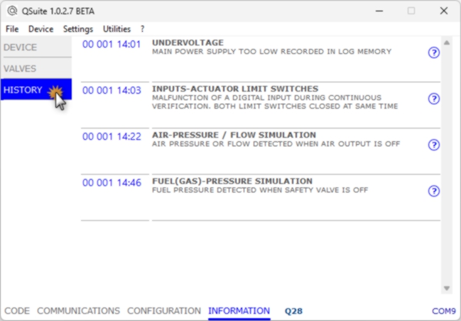
|
|
| This page contains the list of the last 39 lockouts or faults that have occurred and the time at which they occurred (referred to the device's operating time). | |
Additional tools available selecting Utilities from the main menu.
| COMMISSIONING | |
|---|---|
|
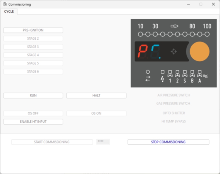
The device can be controlled interactively to facilitate COMMISSIONING operations Enter the first 4 characters of the password [1] and click START COMMISSIONING. 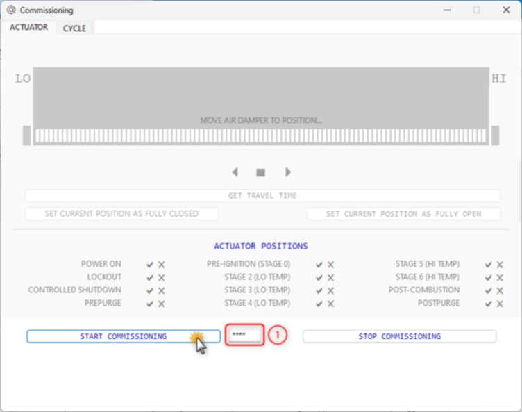
|
|
| In the ACTUATOR tab you can acquire the characteristics of the servomotor and control its position manually, possibly assigning predefined positions in the various stages. | |
|
|
| In the CYCLE tab you can start, stop and advance the operating cycle manually to conveniently carry out the burner setup operations. | |
| VALVE PROVING SYSTEM | |
|---|---|
|
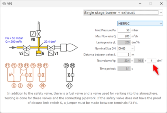
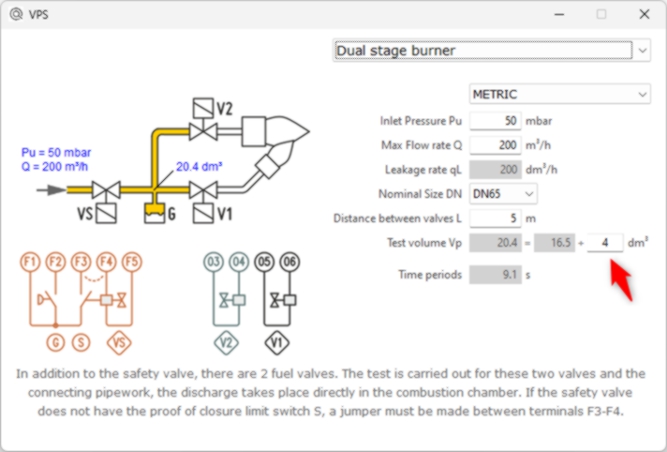
Utility that simplifies the calculation of test time for VPS It is possible to select 4 different pipework configurations. 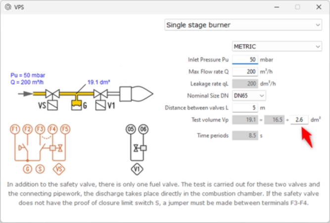
|
|
|
|
|
|
|
|